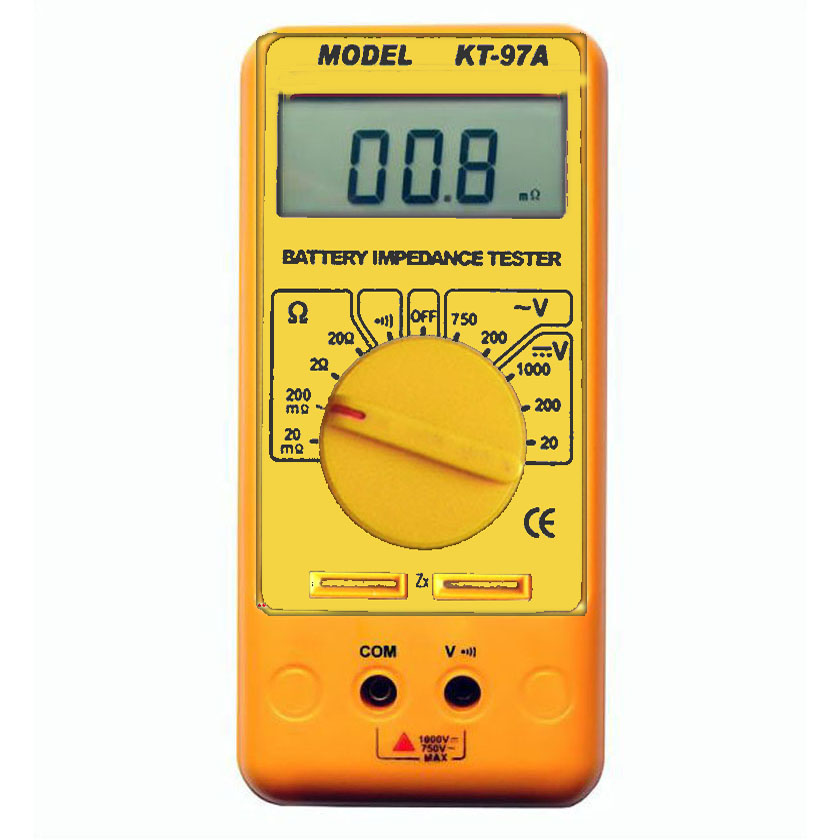
| KT-97A Battery Impedance Tester(update to KT-97B) |
|
|
|
3 1/2 digits, Max. reading 1999
Test battery Impedance, resolution up to 0.01m¦¸
Test Voltage online
Fit to test battery: lead-acid, Li-ion; Ni-HM, etc
Test the battery used in UPS,automotive,mobile phone,etc
Pure AC 1,000Hz test mode
4 wire test clip with high accuracy
Specification
|
Specifications
|
Range
| Resolution
|
Accuracy ˇŔ(%rdg+dgts) |
| Resistance
| 20m/200m/2/20¦¸
| 0.01m/0.1m/0.001/0.01¦¸
| 1.0%rdg+2d |
| DC Voltage
| 20/200/1000V
| 10m/100m/1V
| 1.0%rdg+1d |
| AC Voltage
| 200/750V
| 1000m/1V
| 1.5%rdg+10d |
| Continuity
| If the resistance is less than 50 ¦¸,the beeper will sound continuously |
| Weight
| Approx.280g (including battery) |
| Dimensions
| 182mm(L) x 86mm(W) x 38mm(H) |
| Accessories
| "4 wire" test leads ," 2 wire" test leads ,instruction manual ,holster ,color box |
|
| Battery impedance test |
|
1. Plug the 4 wire test leads(clip or pin type probe) into the sockets marked with ˇ°Wˇ±.
Connect the 2 test clip together, you may get the reading on the LCD.It may be zero or very close to zero. Adjust ˇ°0ˇ± knob with a small screw driver to get zero reading.
|
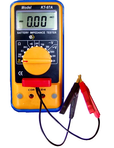
Click for large phto |
|
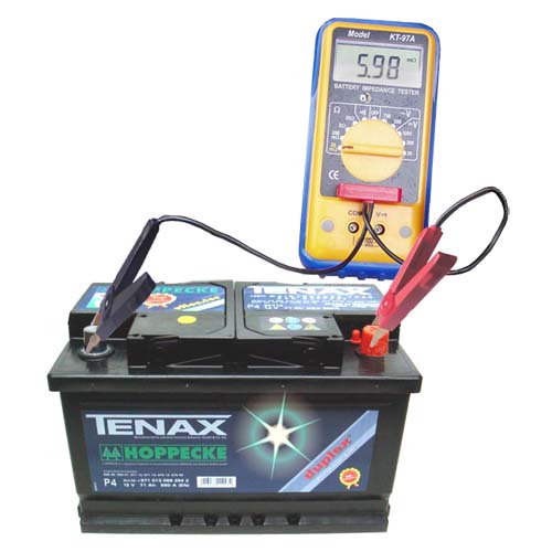
Click for large photo |
2. Connect the two clips to the battery under test. The red lead clips the positive pole of the battery; the black one clips to the negative ploe of the battery.Wait about 10 seconds,until the reading is steady.Then, you can get the impedance value on LCD. If the reading is over range. Set the range switch to a higher one.If the reading is too small,move the range switch to a lower one. |
|
3 wire probe. We can provide this high performance probe as accessory.
The pin type probe has a flexible cord. This cord can be replaced when it doesn't work.
|
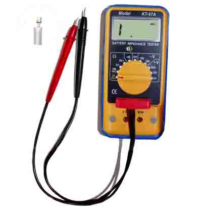
Click for large photo |
|
Voltage Measurement
(Use 2 wires test leads)
1. Set the power switch to the ˇ°onˇ± position.
2. Connect the red lead to ˇ°V. ˇ± terminal, and the black lead to ˇ°COMˇ± terminal. Then set the switch to AC or DC position.
3. Set the Rotary switch to the appropriate range for the voltage test. If the voltage is unknown, start with the highest range.
4. Connect the two test leads to the circuit.
5. Read the value display on the LCD. If only displays ˇ°1ˇ±, means over range. Move the range switch to the next higher range.
Continuity Test
1. Set the power switch to the ˇ°onˇ± position.
2. Set the switch to the beep position.
3. Open the circuit under test before connecting the two test leads.
4. Connect these two test leads to the test circuit. When the resistance is less than 50¦¸, the beeper will sound continuously. | |
|