
Software screenshot
measure more than two cord Cable
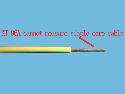
cannot measure single cord Cable
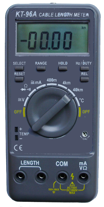
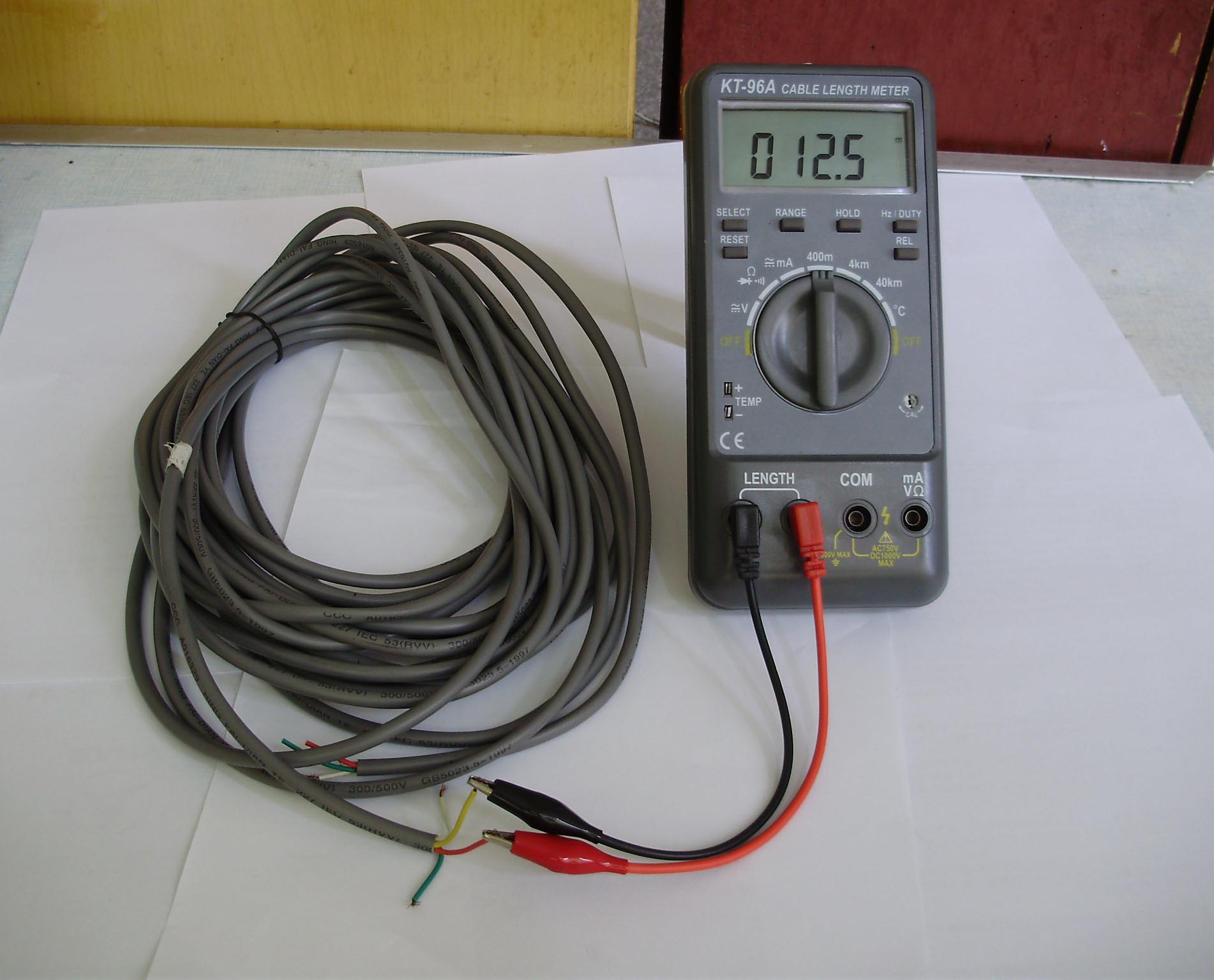
- LCD Max. Indication 3999,with length unit.
- Locate the broken point of a cable. With RS-232 interface, it can be connected to your computer.
- Takes a new “VECTOR MEASUREMENT” technology in measuring the length of the cable.
- Length Test Range:400m/4000m/40km
Accuracy: ±1% rdg ± 0.3m
- For use in computer network, CATV, communicate engineering
- With Voltage, Resistance,continuity,diode test
- This meter takes a capacitance measurement.It is used to test the cable which is more than two cord or wires in it.
| Specifications |
Range |
Accuracy±(rdg+digits) |
| Length |
400m |
± 1.0% rdg ± 0.3m |
| 4000m |
± 1.0% rdg ± 2m |
| 40Km |
± 1.0% rdg ± 20m |
| DC Voltage |
400mV |
± (1.0% rdg +2) |
| 4V/40V /400V/1000V |
± (0.8% rdg +2) |
| AC Voltage |
400mV |
± (1.8% rdg +5) |
| 4V/40V/400V |
± (1.0% rdg +3) |
| 750V |
± (1.5% rdg +3) |
| Temperature |
0 ∼ 400 ℃ |
1.0% rdg ± 3d |
| 400 ∼ 750 ℃ |
2.0% rdg ± 15d |
| DC Current |
40mA/400mA |
± (1.5% rdg +2) |
| 20A |
± (2.0% rdg +3) |
| AC Current |
40mA/400mA |
± (2.0% rdg +3) |
| 20A |
± (2.5% rdg +5) |
| Resistance |
400/4k/40k/400k/4MΩ |
± (1.0% rdg +2) |
| 40MΩ |
± (1.5% rdg +2) |
| Capacitance |
4nF |
± (5.0% rdg +25) |
| 40nF |
± (2.5% rdg +10) |
| 400nF/4μF/40μF |
± ( 2.0% rdg + 4) |
| 200 μ F (100 μ F) |
Unspecified > 30Sec |
| Diode |
Display read approx. Forward voltage of diode. |
| Continuity |
If the resistance is less than 50Ω, the beeper sounds continuously |
| Overload Indication |
"1" on MSB, others blanked |
| Operating Environment |
0℃∼40℃,<80% R.H |
| Storage Environment |
-20℃∼60℃,<80% R.H |
| Power Consumption |
About 5 mA |
| Power Supply |
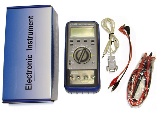
R6UM3 "AA"1.5V×2 battery |
| Dimensions |
182mm×86mm×38mm |
| Weight |
approx. 280g ( including battery ) |
| pcs/carton |
20 |
| N.W.(kg) |
6kg |
| G.W.(kg) |
7.2kg |
| Packing carton size |
41(L) x 33(W) x 30(H) cm |
Attention: The above accuracy is just specified by the meter itself, consider of an random error lead by the quality of the cable ,an additional error ,maximum may up to ±2% Length, must be added to the test result.
OPERATION AND MEASUREMENT
1 Length Test
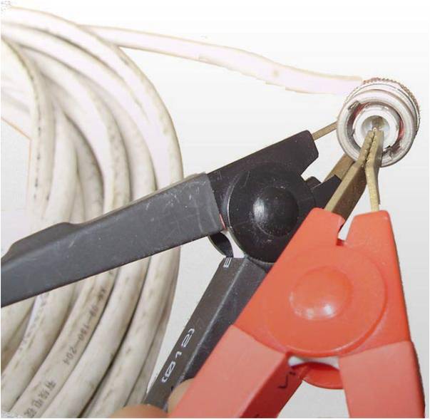
1.1 Be sure to disconnect the cable under test from the active circuit before connecting it to the meter. Confirm that the remote terminal of the cable is open.
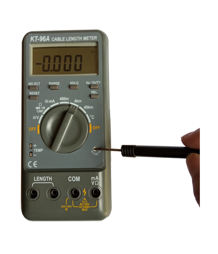
1.3 Measure the unknown cable After you calibrate the length meter, you may use it to test the unknown cable.
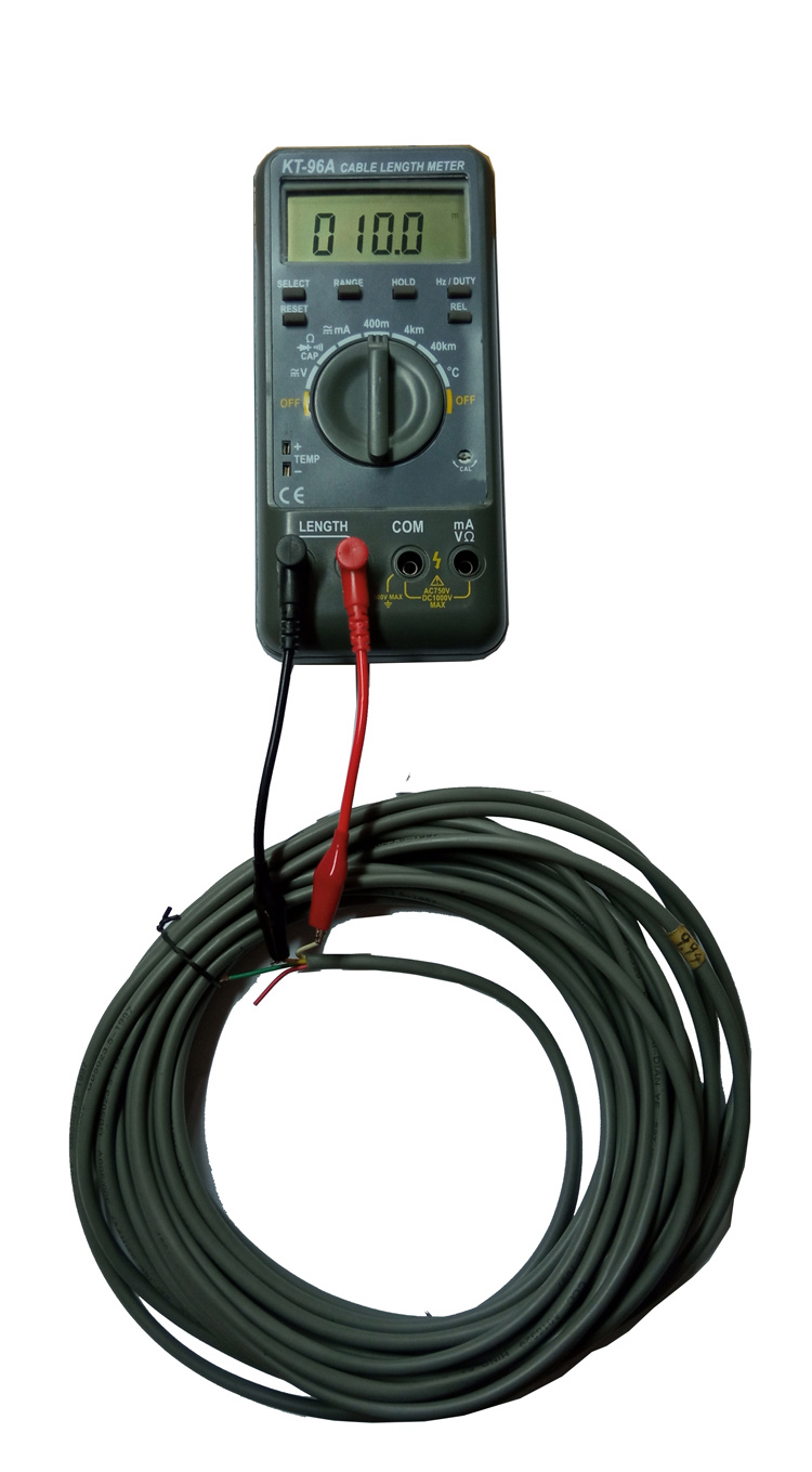
1.3.1 Plug the 4 wire test lead into the socket marked with “Zx”.connect the clips of the test leadto the cable under test. The reading display on the LCD is the length of the cable. If the reading is too small, you may turn the range switch down to get better accuracy. If the LCD displays "1" in the LSB, others blank. This means the test result is overflow, you have to rotate the range switch to turn up the test range.
1.3.2 Locate the broken point of the cable
With the length test function, you may locate the broken point of a long cable. This function may help people to discover the broken point of the cable.
2 Voltage measurement
2.1 Connect the red test lead to the "+" jack and the black test lead to the " - " jack, and select to the AC or DC position.
2.2 If magnitude of voltage is unknown, start the test from the highest range and reduce it until a satisfactory reading is obtained.
3 Diode & Resistance test
3.1 Set the Function switch to the "2KW " position.
3.2 Turn off power to the circuit under test.
3.3 Connect the red test lead to the “+”, the black test lead to the “-”. Touch probes to the diode. A forward voltage drop is about 0.6V (typical for a silicon diode).
3.4 Connect the red test lead to the “+”, the black test lead to the “-”. Touch probes to the diode. The reading "1" is displayed. (typical for a germanium diode).
3.5 When test the resistance which is small than 2KW, the test lead can directly touch the tested resistance, and get reading from the LCD.
4 Continuity test & 200W Test
4.1 Set the Function switch to the "200W " position.
4.2 Turn off power to the circuit under test.
4.3 If the resistance is less than 50W, the beeper sounds continuously.
4.4 When test the resistance which is small than 200W, the test lead can directly touch the tested resistance, and get reading from the LCD.
5. Battery Replacement
5.1 The " " appears on the LCD display when replacement is needed.
5.2 After disconnect the test cable and turn off the power switch, unload the screw on the rear planet. You can separate the rear planet with front planet.
5.3 The battery is located in the battery compartment at the bottom of the front planet.
5.4 Disconnect battery from the instrument and replace with a standard 9V-transistor battery, then close the rear planet cover.